Note- >10 means HEX 10.
Bytes >A->B show the total number of allocation units on the volume. This information should match the Allocation Bit Map data.
Jump to Sector 0,1 and 2 mapping
The Device Service Routine (DSR) ROM in the 99/4a Disk peripheral is designed to give the user access to the disk by means of a system using three different 'levels', which, with the addition of some utility routines gives the user complete access to a normally formatted disk without the need for any knowledge as to how the actual disk controller works.
Each level uses those features implemented at a lower level to add new features, (a sort of 'building block' system).
LEVEL l FEATURES
Communication with the FD1771 chip
Record read/write functions
Disk formatting functions
Soft error corrections
This level is the only level which must know precisely what the
disc hardware is. This allows higher levels to be independent of both
the controller chip type, and the rest of the disc controller hardware.
Each of the higher levels sees the disc simply as a linear storage
device, addressed by disc unit-number, a physical record number, and a
read or write operation.
If the disc controller chip is changed (such as the Myarc card)
then it should only be necessary to replace this part of the software.
All the higher levels are designed to be independent of the actual
physical disc structure which this level deals with, except for sector
size which is assumed to be 256 bytes. Smaller sector sizes could
easily be supported by setting up the sectors in such a way that the
total adds up to 256 bytes - for instance, if a sector size of 64 is
used, each sector requested from a higher level would take up 4 sectors
at level l.
LEVEL 2 FEATURES
All level l features plus:
Creation and deletion of files
File allocation dynamically extendable
Data accessed by filename and physical record displacement
Mixed hybrid file format (see below)
The actual 'file' concept is created at this level, with each file being known by its name and the displacement of the physical record within the file — a physical record being defined as one disc sector (256 bytes).
On each disc is maintained a directory and bit-map of the sectors.
This allows for file and record management (i.e. deletion and creation).
The file format available is called the 'mixed hybrid' format, and is a mixture of contiguous and non—contiguous (fragmented) file formats. A lot of overhead has to be carried by fragmented files in the form of pointers - these pointers are required in case relative access is required to the file and point to each data record of the file.
The files on this level are allocated in 'clusters' of contiguous records in order to combine the advantage of the flexible allocation of non—contiguous files with the low overhead, and the easy access of contiguous files. Whenever new records are requested. the clusters are expanded if possible, if a cluster cannot be expanded then a new one is started.
LEVEL 3 FEATURES
All level 2 features, plus:
Program and data files
Fixed and variable record formats
Relative and sequential access
Internal and ASCII data types
The disc management software is completed by the addition at this level, of the relative/sequential access and the fixed/variable record formats. This level takes care of the 'blocking’ of one or more logical records into a physical record (as with DIS/VAR format), when relative access is required, it computes the physical record in which the logical record is to be found, updates that record and passes the physical record back to the level 2 file update routines.
UTILITY ROUTINES
As you may have noticed, there are some functions which have not been catered for, as they are not part of the normal file I/O system. These are catered for by means of some utility routines. These 'subprograms' are:
Direct level 2 file access
Direct sector (Allocatable unit) access
Modification of file protection
Disk formatting
File rename.
Methods of accessing these routines will be described later.
There are three basic methods used to store data on the diskette.
These are:
l. 'Program' (Memory Image) format
2. Variable format
3. Fixed format
Variable and Fixed format are really 'variations on a theme', in that, each sector, (or AU), contains as many records of either format as it is possible to write to that sector — without overflowing it (i.e without writing more than 256 bytes).
Program format is used to store an image of the data in memory on the diskette byte for byte, each byte in each sector being used (except for the last sector associated with the particular file, which may not be fully used due to the length of the file not being exactly divisible by 256).
Methods of access
There are three methods of access, each one being associated with
one particular format described above. The methods of access are (in
order):
1. Physical I/O
2. Sequential access
3. Relative access
Sequential access
When the data records in a file are accessed strictly in the order
of increasing address on the medium. each record is said to be
'sequentia1ly' accessed. This is the access method used for accessing
such things as magnetic and paper tapes etc, in which all the records up
to and including the one required must be read in order to access the
particular record required. In this mode of access, the parameters for
the data transfer do not specify a physical record number, as it is
implied that the logical record currently indicated by some data
transfer pointer is the one which is required. Restore/rewind
operations are either implicitly done or explicitly done prior to the
first data transfer. As each logical record is transferred, the access
pointer moves to the first byte of the next logical record (which in the
case of this DSR is usually the length indicator).
Sequential access methods have the advantage that variable record lengths can be used (such as the well known "VAR 80") and so the number of records per sector can be increased by an amount dependent on the length of each particular record. For instance, ten 24 byte records could be written on a 256 byte sector, whereas if "FIXED 80" were to be used, then only 3 records (=240 bytes) could be written even though there are still only 24 bytes of usable data per record.
Variable format (sequential access) sectors are recorded on the disc with an extra byte added at the start of each record, and a final byte at the end of the last record of the sector. The first byte of each record indicates the length of the record in bytes, a negative number (usually >FF) indicating that there are no more records on that sector. The action of the computer when reading the sectors from the data buffer in VDP ram is to read the first byte (length of record), then read the required number of bytes as the record from VDP ram to a new location, read the next byte (length of record), etc etc until a negative number is found as the length. At this point another sector is read from the disc to VDP ram and the process repeated again until all the data for the appropriate file has been read.
Relative (Random) access
Relative access allows data in a file recorded in fixed format to
be accessed by logical record number. The records may be accessed in
any order regardless of the order in which they were written or the
order in which they appear in the file.
As the DSR software must be able to locate a record solely by its number, relative access can only be supported on either Indexed Files or Fixed Length files. In this DSR, only "Fixed length" files are supported. (Indexed files are files for which an "lndex" is maintained on the diskette through which a particular record can be located by looking it up in the index.)
Physical I/O With the Physical I/0 access, the data on the disk is considered to be organised in blocks of 256 bytes by the DSR software. Each byte can be of any value (ie -256 to +255) and no attempt is made to interpret these at data transfer. The existence of records or files is completely ignored by this access method.
You will notice that this method of access is a "Level l" access.
The rest of the disc software (i.e., Levels 2 and 3) reduces all access methods to physical I/O by converting logical record numbers into physical track and sector data. This information is used to specify the disc sector that is to be transferred by the Physical I/O. Physical I/O is not available directly to the user other than in the form of an assembly language sub-program within the DSR.
Directory Organisation
The directory organisation implemented within the DSR supports only
a single level directory, that is to say that no FILE can be a directory
containing pointers to other files. This means that each file on the
disc can be readily identified by a single name, e.g.: DSKl.filename
which would specify a file called "filename" on the diskette in drive 1.
This approach to the diskette file organisation prevents access to a catalog file as such on the disc, as no such file can physically exist. In order to overcome this problem, a semi-catalog file can be created by the DSR software and accessed by the user. The file which is created (and remember it is not physically on the disc, so don’t go looking for it with the Disc Manager), is of the Fixed format, relative access type. The file contains 128 records, each containing information about the associated catalog entry and is described in detail below. It can be accessed as: DSK1. or DSK.volname as a standard data file but without a name.
Please note that not all the file operations have been defined for this catalog file, and only the standard OPEN, READ, and CLOSE are supported. Other operations such as DELETE, EOF, etc. are considered to be illegal, and an error will be returned if these operations are used.
Catalog file access from Basic
The Catalog file can be accessed as a read-only file by the Basic
user. The file has no name, and is of the INTERNAL, FIXED format type.
The file can be opened by (for example):
OPEN #l:"DSK.",lNPUT,INTERNAL,RELATlVE
The record length will automatically be defaulted by Basic to the
correct value, so this should not be entered. If however the user wants
to specify the length, then it must be specified as 38 - all other
lengths will result in an error message.
The Catalog file acts as if it is Protected, and as mentioned above, it will only allow INPUT access.
The file is written in the normal Basic INTERNAL format, and each record contains four items: one string and three numerics. There are 128 records in the file, and they are numbered 0 thru 127.
Record 0:
This record contains data about the volume for which the catalog
file was created. The string gives the name of the disc (up to 10
characters) and the numerical items are as follows:
1. Always 0 (for record 0)
2. Total number of sectors on the disc
3. Total number of free sectors on the disc
Records 1 thru 127:
These records contain information on the corresponding file in the
Catalog. Non existant files will give a null string for the first item,
and 0’s (zeros) for the numeric items. Files which exist will give the
file name for the string, and the following numeric items:
1. = Filetype (if number is negative, file is protected)
            1= DISPLAY/FIXED datafile

               2= DISPLAY/VARIABLE datafile

               3= INTERNAL/FIXED datafile

               4= INTERNAL/VARIABLE datafile

               5= Memory Image file (Program File)
2. = Number of AUs allocated to the file
3. = Number of bytes per record (0 for type 5 file)
The information in the records is as follows:
l. An ASCII string of up to IO characters containing the name of
the file in the specified slot. For record 0 this is the
Volume name.
2. A floating point value of between -5 and +5. These values
represent the same information as given for Basic.
3. The number of AUs allocated for the file (record 0 = total
AUs on the disc)
4. The number of bytes per logical record - 0 for Program file.
(Record 0 = Free AUs remaining on the disc)
If a catalog slot is empty, the filename will contain a null string
and the numeric entries will contain floating point zeros.
The physical record length is the size of the block of data which can be read or written to the device at one time. For the Disc Peripheral, the AU and the Physical Record are equivalent to one disc sector (256 bytes).
Summary of system reserved sectors:
Sector 0 contains data concerning the volume, such as available
(free) sectors, disc name etc.
Sector 1 contains pointers to other sectors which contain
descriptions of the appropriate file. Normally there is a pointer
in sector one for each file which exists on the disc.
Volume information block (VIB), Sector 0
This block contains disc configuration data as required by the disc
software. This includes available number of AUs, Volume name, format
information etc. Included in this block is the "Allocation Bit Map":
The allocation bit map is used to indicate to the disc software the
availability of individual sectors on the disc. A "l" indicates that
the sector associated with that "bit" has been allocated, and a "0" that
the sector is available for use. The first bit in the map is for sector
0, the second for sector I and so forth. when the disc is initialised
(WITH VERIFY = YES if using DM1000 or similar), then the bits for bad
AUs are set to "l" along with the bits for non-existant AUs and the 2
system reserved AUs. All the remaining bits are of course set to zero.
File Descriptor Index Record (FDI), Sector 1
This sector contains alphabetically sorted pointers to each File
Descriptor Record (FDR), and enables the system to keep track of the
location of each FDR on the disc.
NOTE: If either Sector 0 (VIB) or sector 1 (FDR) are bad or corrupted then the whole disc is considered bad by the system, as it can no longer keep track of information stored on the disc.
File Descriptor Record (FDR) - Any Sector
This record is used to map filenames into physical locations of the
files on the disc. Each entry contains information about the file such
as type, record type, data type, size of file, etc.
File Control Block (FCB) in VDR RAM
This is a copy of the FDR which is maintained in VDR RAM while the
file is open. It may additionally contain some more up-todate
information about the file. One FCB is required for each file which is
currently opened. It is the memory taken by these FCBs which is
affected when "CALL FlLES" is used in BASIC.
The capacities given are for a single sided, single density system. Using double sided will of course double the bytes per disc, using double density (Myarc type controller) will double the capacity again.
For ease of description, the following information assumes that the diskette is addressed as a 'linear' medium, that is to say, sector 0 is the first sector of track zero, sector 1 is the second and so on -- sector 359 being the last sector of track 39. It should be noted that this is not strictly correct as the sectors are in fact interleaved on each track to obtain faster access when reading. If a double sided set up is being used then the physical layout of the second side is the reverse of the first side, that is to say, sector 360 is physically on the opposite side of the disc to sector 359, and sector 7l9 is opposite sector 0.
.
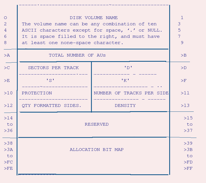
VOLUME INFORMATION BLOCK LAYOUT
Note- >10 means HEX 10.
Bytes >A->B show the total number of allocation units on the
volume. This information should match the Allocation Bit Map data.
Bytes >D->F contain the ASCII letters 'DSK'. These letters are checked by the T.I. disc managers to see if the disc has been initialised.
Byte >10 Contains the ASCII 'P' if the disc is Proprietary Protected. This byte will normally otherwise be an ASCII space.
Bytes >12->37 are reserved for what were intended to be future expansion. This could be date and time of creation etc. The T.I. controller will set all these to zero.
Bytes >3B->FF contain the allocation bit map. The map can control up to 1600 256-byte sectors (=400K bytes) - this will allow double sided, double density diskettes without modification to the map layout.
Each bit in the map represents one sector on the disc. A logical one in the bit map means that the corresponding sector has been allocated, a logical aero means that the sector is available for use.
The Volume name can be used as an alternative to the drive name -
that is to say the user can specify a disk drive in either of the
following ways:
DSK.volname.filename or DSKl.filename
If the volume name is specified, then the system will look at each drive in sequence until it finds the specified volume. If more than one drive contains a volume with that name, then the lowest drive number will be assigned.
FILE DESCRIPTOR INDEX RECORD, (Sector l)
This sector contains up to 127 two-byte entries. Each of these
points to a File Descriptor Record, and are alphabetically sorted
according to the file name in the File Descriptor Record. The list
starts at the beginning of the block, and ends with a zero entry.
As the file descriptors are alphabetically sorted, a binary search can be used to find any given filename. This limits the maximum number of searches to 7 if more than 63 files are defined. Generally if between 2**(N-1) and 2**n files are defined, a file search will take at the most N disc searches. To obtain faster directory response times, data blocks are normally allocated in the area above sector 222, the area below this being used for file descriptors and only used for file data when there are no more sectors available above >22.
File Descriptor Records
The File Descriptor Record (FDR) contains the general information for its associated file. In order for the system to function, all the information to access and update the file must be contained within this record.
Layout of an FDR is as follows:

Bytes >A and >B were reserved for an extension of the number of
data chain pointers. As this was never implemented, these
bytes are always 0.
Byte >C The file status flags are as follows, where Bit O is the LSB:
Bit No. Description
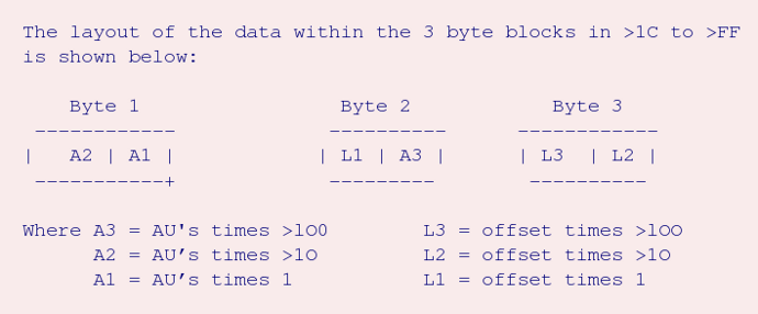
The layout of the data within the 3 byte blocks in >1C to >FF
0 ... File type indicator.
........ 0 = Data file
........ 1 = Program file
1 ... Data type indicator
........ 0 = ASCII data (DISPLAY file)
........ 1 = Binary data (INTERNAL or PROGRAM file)
2 ... This bit was reserved for expansion of the data
... type indicator.
3 ... PROTECT FLAG
........ 0 = NOT protected
........ 1 = Protected
4,5 and 6 These bits were reserved for expansion of ????
7 .... Fixed/variable flag
........ 0 = Fixed record lengths
........ 1 = Variable record lengths
Bytes >E and >F The number of 256 byte records allocated on
........ level 2.
Byte >10 Contains the EOF offset within the highest
.... physical AU for variable length records and
.... program files.
Byte >11 Contains the logical record size in bytes. For
.... variable length records this byte contains the
.... maximum permissible record size.
Bytes >12 and >13 Contain the number of records allocated on level
............. 3. For variable length records these bytes
............. will contain the number of level 2 records
............. actually used. NOTE: these bytes are in the
............. reverse order.
Bytes >14 to >1B These bytes were reserved for future expansion,
............... and will always be 0.
Bytes >1C to >FF Contain blocks of three bytes which indicate the
............... clusters which have been allocated for the file.
............... 12 bits of each 3 byte block indicate the
............... address of the first AU in the cluster, and the
............... remaining 12 bits indicate the highest logical
............... record offset in the cluster of contiguous
............... records (This method of indication reduces the
............... computation required for relative record file
............... access).
is shown below:
Also refer to Data from TI*MES 13
ALLOCATION FOR DATA FILES
A Data file is built of clusters of contiguous data records, each
date file can contain up to 76 of these data record clusters, with each
cluster containing at least one data record. The DSR software will
allocate as many contiguous records as possible upon request, - if a new
record is requested and no more records can be added to the current
cluster, then a new cluster of contiguous records is started. If 76
clusters have been allocated and a new cluster is requested then the
write operation will be aborted. This will only occur when the data
records on the disc have become too scattered (i.e. the file is badly
segmented) - the problem can be corrected by copying the disc with the
disc manager (or with DMIOOO in file mode), which will cause the records
for the files to be allocated in l (or at the most 2) clusters on the
new disc. Note that at worst case this scheme still allows for 19k
bytes per file (76 * 256 bytes).
Because of the system used, each physical record within the file can be accessed at random, without any need for large areas of contiguous disc space. This means that so long as the logical records within a file have a fixed length, the file can be accessed either at random or sequentially, and therefore the disc software does not have to distinguish between relative record and sequential files. This has some implication for sequential fixed length record access, as now the record number is being used, rather than the current record number and offset.
For variable length records, the length of the logical record is stored at the start of the record itself. The result of this is that (since a record cannot cross an AU sector boundary), the maximum record length for variable length records is limited to 254 bytes, as the 'end of records on this sector' (>FF) has to be written too.
PROGRAM FILE ALLOCATION
Program file allocation is identical to data file allocation. The
Program file (segment) is split into 256 byte records which are stored
as a standard data file. As the disc software marks the file as a
program file it can prevent data access to program files (and vice
versa).
In order to prevent problems with VDP ram 'wrap round' (i.e. continuing to write to VDP ram after address >3FFF will write to >0000) the DSR software notes the actual number of bytes used in the last data record and will return exactly as many bytes as were originally written to the disc, even though this may not be a multiple of 256.
This web page contains the combined text of two articles published in East Anglia Region 99'er User Group published October and November 1988, written by Colin Hinson, regarding the way the TI-99/4a stored its programs and files on disk.
Also see: Disk Peripheral DSR Mapping
[ TI Book front page |
TI Resources Page
| TI99/4a articles
| PC99 and MESS Programs
]